#1 Induction Loops & Photocells Replacement
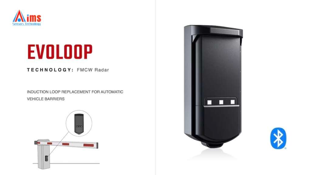
Designed and launched by BEA recently, EVOLOOP is a replacement for induction loops and photocells, making the installation and setup of automatic vehicle barriers simple and hassle-free. No more ground cutting or dusty construction work.
In this article, we’ll walk you through the key steps to install and configure your EVOLOOP, so you can get your automatic vehicle barrier up and running in hours, not days.
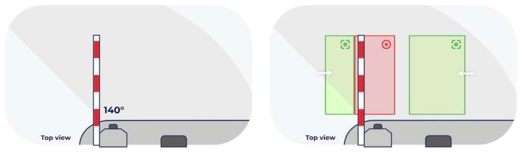
EVOLOOP is an FMCW-based sensor designed for presence and protection detection on automatic vehicle barriers. Within its 140-degree field of view, you can configure up to three virtual loops independently. Depending on your needs, choose between presence loops for activation or closing, and protection loops.
Key Benefits of EVOLOOP:
- CLEAN & INSTALLER-FRIENDLY: No ground-cutting or dusty work - faster, cleaner installation that saves time and money.
- EASY & QUICK SETUP: Connect and configure everything directly from the mobile app.
- RELIABLE PROTECTION: Safeguards both vehicles and pedestrians in real time.
- PRECISE 3D DETECTION: Up to 7M range with 140° horizontal and 40° elevation field of view.
- TOTALLY VERSATILE: Compatible with all barrier types and lengths, in any weather and environment.
#2 EVOLOOP Installation in 6 Simple Steps
In just 6 steps, you can install and configure EVOLOOP, getting your automatic vehicle barriers up and running quickly.
Note: Please carefully read the User Guide before installing EVOLOOP. You can find all relevant documents in the #4 Document Downloads section below.
Step 1: Mounting - Position and Secure the Sensor
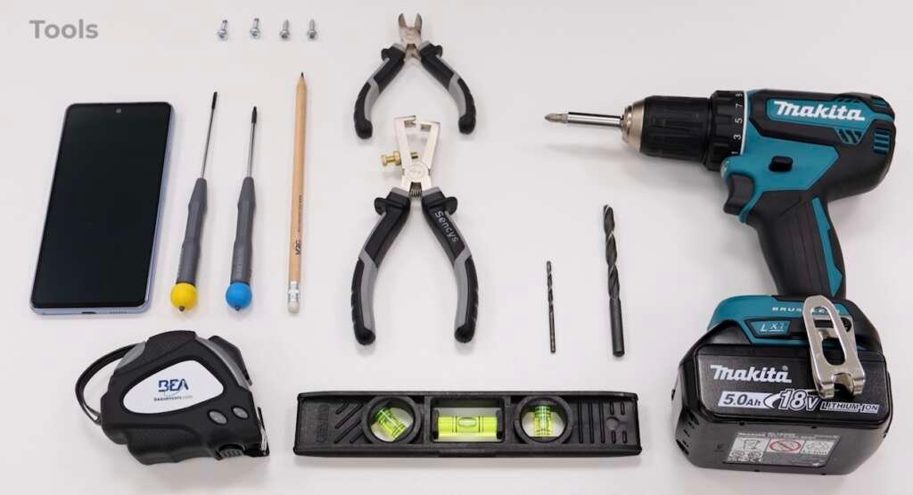
Begin by removing the protective cover from the mounting support. Insert a screwdriver into the notch at the bottom of the product and gently lever it up. For the metallic version, unscrew the cover first. Then, push the sensor upwards to detach it from the mounting support.
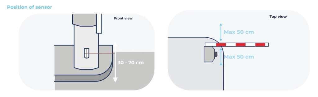
Before installation, make sure the sensor is mounted at 30–70 cm above road level. If the sensor is being used to protect against collision with the barrier boom, install it at a maximum distance of 50 cm from the boom (as illustrated in the diagram below). Use the mounting template to position the sensor correctly.
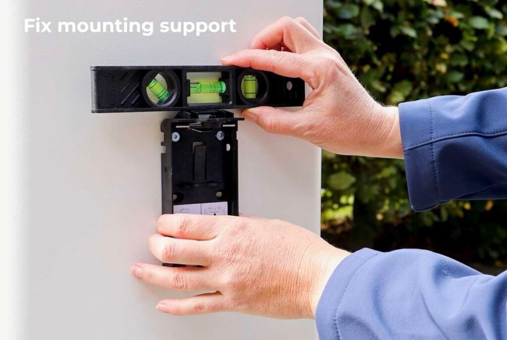
Drill an 8 mm hole for the cable, and drill the remaining holes if you are not using self-drilling screws. You may remove the transparent mounting template afterwards, or leave it in place. Fix the mounting support to the cabinet using your own screws, ensuring the screw head is not larger than the hole. A spirit level can help you align the sensor straight.
Next, pass the cable through the hole, leaving about 10 cm of cable between the hole and the plug. Remove the sliding cover by lowering it first, then placing your finger behind it and pulling it off. Insert the plug into the sensor socket and secure the connector firmly with one of the provided screws.
Finally, place the sensor back onto the mounting support by inserting the top first, then the bottom. Make sure the cable is neatly pushed in, the sensor is firmly fixed, and the orientation matches the traffic flow. Adjust the direction as needed by lifting and rotating the sensor. No additional accessories are required. Once done, slide the cover back into place.
Step 2: Wiring - Connect the Sensor to the Barrier System
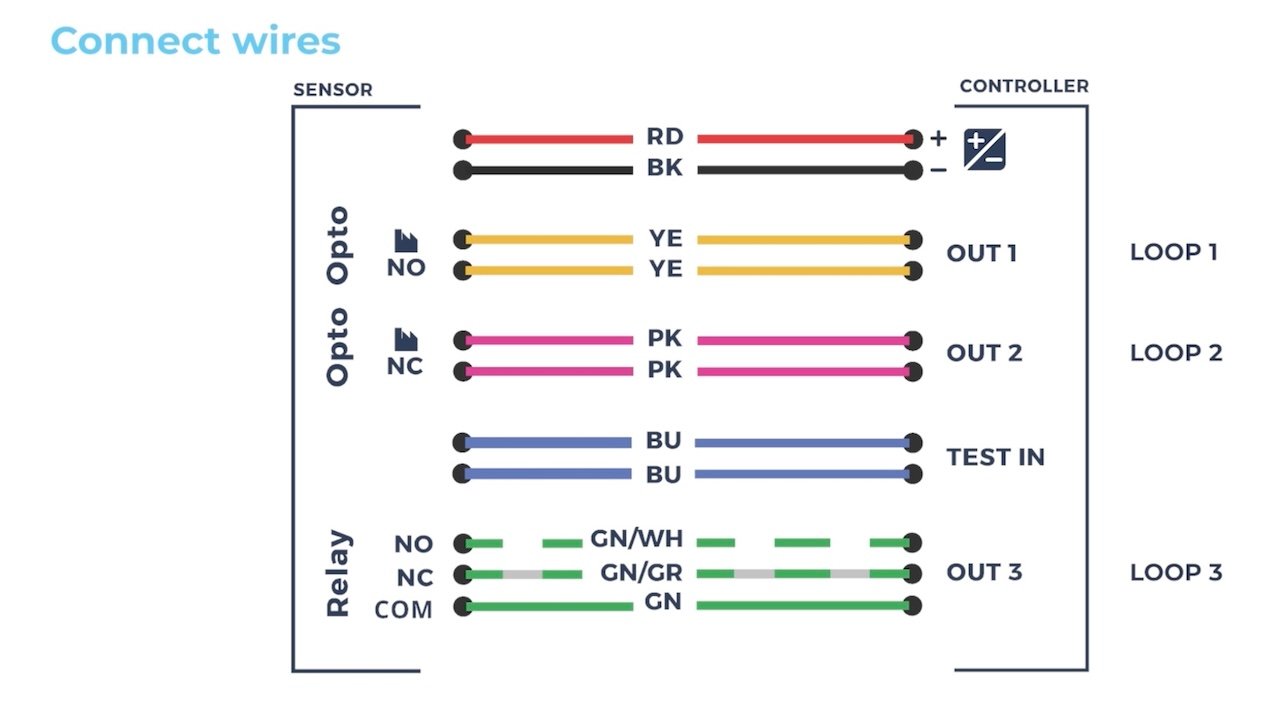
Connect the wires according to the wiring diagram shown below.
Loops 1, 2, and 3 correspond to outputs 1, 2, and 3. Each loop can be assigned a specific function depending on your setup: presence for activation or closing, or protection.
Make sure each connection is made correctly to ensure proper sensor operation and reliable barrier performance.
Step 3. Connect via Mobile App - Pair EVOLOOP with the Everloop App
Open the EVOLOOP app and connect it to the sensor. The default password is shown on the label supplied with the unit, and you can change it later for added security.
During pairing, the Bluetooth LED blinks rapidly, then turns solid once the sensor is successfully paired. Bluetooth stays active while the sensor is connected to the app, or for up to 30 minutes if no app connection is established.
Note: The app not only makes it easy to set up and configure EVOLOOP, but also allows us to monitor the sensor afterward.
Step 4. Teach-in - Learn the Environment and Boom Movement
Before starting the teach-in process, make sure the barrier is open, the area is clear of objects, and you are standing outside the detection field. No vehicles or pedestrians should pass through the area during this procedure.
If the sensor is being used for the first time or has been reset to factory settings, the orange LEDs will blink and the outputs will be activated. Start the teach-in process through the app. You can also launch it using the push buttons; please refer to the user guide for details.
During the first phase, the sensor learns its environment and the first LED blinks red and green. Once this is complete, the boom will automatically close and reopen if the wiring and configuration allow it. If not, you will need to do this manually. This step is essential, as it allows the sensor to learn the boom movement and detect additional elements such as skirts or pendulums.
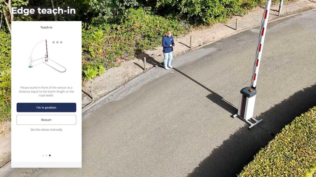
Wait until the boom has stabilized. After the boom movement teach-in is completed successfully, EVOLOOP will ask you to indicate the boom length. Move to a position in front of the sensor at a distance equal to the boom length or the road width (as illustrated in the picture below).
While the sensor is waiting for you, the green LEDs will blink. Stand still until the LEDs turn red, which confirms that the sensor has locked your position and the process is complete. A full teach-in summary is available in the app.
Step 5. Select the Virtual Loop Configuration - Choose the Preset That Matches Your Application
Now that the sensor has learned its environment, you can select a virtual loop configuration that best fits your installation. EVOLOOP offers five preset options, each designed for a different use case:
- Preset 1: Factory settings with one activation loop and one protection loop.
- Preset 2: Paid parking with one activation loop and one closing loop. This configuration is ideal for the passage control feature. More information is provided in the description below.
- Preset 3: Entry, protection, and exit with activation loops on both sides and one protection loop.
- Preset 4: Protection with one protection loop.
- Preset 5: Paid parking and protection with one activation loop, one protection loop, and one closing loop.
Please note that the rotation angle varies depending on the selected preset.
TIP: Loop Teach-in
If needed, you can configure up to three virtual loops individually. To do this, start a loop teach-in and select the loop you want to set up in the app.
When the green LEDs begin blinking slowly, go to the center of the desired loop and remain still. Once the red LEDs start blinking, the loop teach-in has been completed successfully.
Step 6. Loop Settings
If needed, you can change the loop type from presence to protection, or vice versa. You can also adjust the loop dimensions to match your application. The default loop depth is set to 1.5 m, and the width corresponds to the distance learned during the edge teach-in.
The maximum size for a presence loop is 7 m x 7 m. In general, we recommend setting virtual loops slightly larger than a traditional induction loop. For presence loops, you can also select the target type, depending on whether you want to detect vehicles only or both pedestrians and vehicles.
If required, you can also add a sense of direction to further refine the installation. Be sure to press Apply at the end of each change to save your settings.
Tip: App Features
Through the app, you can easily save, reuse, and share your preferred loop settings. You can also generate and share an installation report with colleagues. If you want to explore the interface or prepare settings before installation, use Demo Mode without connecting to the sensor.
Once configuration is complete, replace the sliding cover and the protective cover. Secure them with the Torx 10 screw for added protection. If desired, you can also turn off the LEDs via the app.
Before leaving the site, make sure to check the installation.
Tip: Viewer
The Viewer makes it easy to verify your loop configuration, including the position of detected targets.
#3 EVOLOOP Quick Tutorial Video
You can also watch the EVOLOOP Quick Tutorial video on YouTube for a step-by-step guide on how to install and set up everything. The video is available in both English and Cantonese, making it easy to follow in your preferred language.
Quick Tutorial Video
Click above to watch the EVOLOOP Quick Tutorial Video on YouTube.
#4 Document Downloads
You can download the latest EVOLOOP pdf documents here below. Currently available in English, these documents provide everything you need for installation, configuration, and product information.
#5 Contact Us
From vehicle access control and counting to dimension measurement, advanced vehicle classification, micro-object detection, and custom sensing solutions, our in-house engineering teams in AI, optics, software, and electrical design can turn unique concepts into end-to-end sensing solutions. Whether you need support with your EVOLOOP installation or have a project idea in mind, contact us — we’ll be happy to help.